The Attributes tab allows users to enter general information about the conduit, such as owner, location, pipe shape, and line type. Some fields have special uses. These fields are described in the table below:
Field |
Function |
Pipe Shape |
It has a pre-defined list of shapes. Although shapes can be added to the list the pre-defined ones cannot be modified. |
Dia/Height (in) |
Enter the diameter of a round pipe in inches. If the pipe is not round, enter the height in inches. |
Width (in) |
Enter the Pipe width in inches. This field is for when the Pipe Shape is not round. |
Lt Side Slope |
The approximate ratio of rise to run of the left bank of an open channel while looking from upstream to downstream. |
Rt Side Slope |
The approximate ratio of rise to run of the right bank of an open channel while looking from upstream to downstream. |
Length |
The length of the conduit from center of a drainage structure to center of a drainage structure in feet. |
Length Status |
The source used to find the conduit length (i.e. record drawings, as-built, TV inspection). |
Slope % |
Slope refers to the vertical displacement along the length of the pipe with respect to the horizontal displacement along the length of the pipe (otherwise known as the rise/run). If the Record US Invert and Record DS Invert on the Elevations Tab and Length field on the Attributes tab are filled out, this field will be auto-calculated using the following formula. Slope % = [(Record US Invert - Record DS Invert) / Length] x 100 Note: If any of these three values do not exist in the record, a slope value can be manually. Note: In Edit Mode click in the field and press F5 to recalculate the value. |
Manning's "n" |
This refers to a value assigned to a pipe based on its interior roughness. |
Capacity |
Capacity refers to the maximum amount of flow the pipe is capable of holding (in cubic feet per second). |
Subtype Text |
This field is automatically populated if subtypes are defined in the GIS system. This field is only editable in a GIS geodatabase environment. If the system is not integrated with GIS, this field will not be available. |
Last Cleaning Date |
Users enter the date that the conduit was last cleaned. This is used to calculate the Next Cleaning Date. |
Cleaning Freq |
Enter a number for how often the conduit should be cleaned. The amount of time this number represents is controlled by the Cleaning Freq Units. |
Cleaning Freq Units |
The amount of time represented by the number in the Cleaning Frequency. Click the field caption button or press F9 for the pick-list. |
Next Cleaning Date |
Users can enter the next date that the conduit should be cleaned. If the Last Cleaning Date, Cleaning Freq, and Cleaning Freq Units fields are filled out, this will auto-calculate. |
The Attributes tab also has a Multiple Conduits grid. This allows users to enter other conduits that reside at the same location and share the same physical attributes (materials, slope, etc.)
A sample of the grid appears below. Sort records in the grid by clicking on the headings. An up or down arrow (highlighted in orange below) will appear signifying ascending or descending order.
![]()
How To Add a conduit
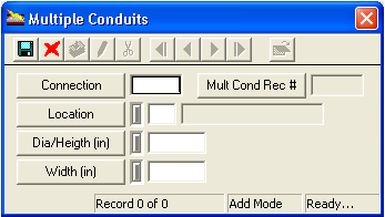
Note: The Mult Cond Rec # field is automatically populated by the system.